正文
Minimize Voltage Offsets in Pr
[10-21 14:57:44] 来源:http://www.592dz.com 模拟电子技术 阅读:9689次
概要:ude precision integrated resistors, but they also switch between the resistors. When the resistors are used to set gain in an op-amp circuit, this capability allows you to choose among programmable gains of 1, 2, 4, and 8.Data sheets for these devices show that they exhibit constant resistance at the resistor-pair node for resistor ratios of 2, 4, and 8. If the ratio is 1, you see only the low resistance of the node. For all ratios, therefore, the matching resistor should equal the wiper resistance (Table 1).Table 1. Matching Resistor Settings
Minimize Voltage Offsets in Pr,http://www.592dz.comYou can use either integrated or discrete resistors in the precision op-amp circuit of Figure 3.
Integrated Resistors
The MAX5421 (as an example) includes 15kΩ resistors and operates with a supply voltage of +5V or -5V. A similar part, the MAX5431, includes 57kΩ resistors and operates with a supply voltage of +15V or -15V. These devices not only include precision integrated resistors, but they also switch between the resistors. When the resistors are used to set gain in an op-amp circuit, this capability allows you to choose among programmable gains of 1, 2, 4, and 8.Data sheets for these devices show that they exhibit constant resistance at the resistor-pair node for resistor ratios of 2, 4, and 8. If the ratio is 1, you see only the low resistance of the node. For all ratios, therefore, the matching resistor should equal the wiper resistance (Table 1).
Table 1. Matching Resistor Settings for MAX5421/MAX5431 Dividers
| MAX5421 (VDD = +5V, VSS = -5V) |
MAX5431 (VDD = +15V, VSS = -15V) | ||
| Wiper Resistance (kΩ, typ) | Rati 1 | 0.3 | 0.5 |
| Rati 2, 4, 8 | 8 | 14 | |
| Matching Resistance (kΩ, typ) | Rati 1 | 0.3 | 0.5 |
| Rati 2, 4, 8 | 8 | 14 | |
Resistor tolerances are shown in Table 2.
Table 2. Resistor Tolerances for MAX5421/MAX5431 Dividers
| Part | Divider Ratio Accuracy (±%, max) |
| MAX5421_A | 0.025 |
| MAX5421_B | 0.09 |
| MAX5421_C | 0.5 |
| MAX5431_A | 0.025 |
| MAX5431_B | 0.09 |
| MAX5431_C | 0.5 |
Note that these tolerances are guaranteed maximums over the full operating temperature range of -40°C to +85°C, which in turn guarantees the gain tolerance to a high level of precision. A typical integrated-resistor design (a precision amplifier) is shown in Figure 4.

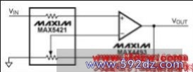
Figure 4. This precision amplifier combines precision resistors (MAX5421 ICs) with a general-purpose, rail-to-rail op amp (the MAX4495).
The main technical advantages of integrated resistor chips like the MAX5421 or MAX5431 are matching and temperature tracking between the resistors. You can then select a desired system gain by electronically switching among the gain-setting resistors.
The absolute resistance of an integrated resistor has a large tolerance. That is not a problem in these circuits, however, because gain values are precisely set by resistor ratios to within ±0.025%. If the matching resistor is external, you will have difficulty choosing the correct value, but integrated matching resistors make the task easy. Integrated resistors can be factory trimmed, and they track the gain-setting resistors precisely with temperature. Any tolerance in R1 and R2 also affects R3, so R3 should match the parallel combination of R1 and R2.
If your system does not require R3, you may be able to reduce costs by using digitally programmable, precision voltage-dividers like the MAX5420 and MAX5430. These devices have the same performance as the MAX5421 and MAX5431, but do not contain the matching resistor. For fixed-gain applications, consider the MAX5490, MAX5491, and MAX5492 resistor-dividers, which contain one fixed-ratio pair of resistors only and no matching resistor.
Discrete-Resistor Approach
Now, consider the gain-setting resistors for an alternate, discrete-component approach. The pair of discrete resistors must not only have a ratio tolerance of ±0.025%, but they must also track within this tolerance over the required temperature range. In practice, this means that each resistor must have a tolerance of 0.0125%. Resistor data sheets often specify an initial tolerance plus a temperature coefficient. We can therefore calculate the worst-case tolerance over the temperature range in question. The example below is based on specifications for an ultra-precision discrete resistor with a low temperature coefficient:
标签:模拟电子技术,模拟电子技术基础大全,模拟电子电路,模拟电子技术
《Minimize Voltage Offsets in Pr》相关文章
分类导航
- 最新《模拟电子技术》
- 热门《模拟电子技术》