正文
Surge Testing Solid-State USB
[10-21 14:57:44] 来源:http://www.592dz.com 电源管理 阅读:9343次
概要: appeared in the October 2008 issue of Power Electronics Technology magazine.IntroductionWith a 1.2A current limit one would think that a circuit-protection IC could maintain complete control in the event of a fault or short. The reality is that the current limit usually demonstrates a delay time before the actual shutoff occurs. During a hard short, the current can rise very rapidly, first hitting the DC limit and starting to turn the switch off. (The DC limit is typically an accurate, but slow threshold. A slow threshold avoids nuisance trips
Surge Testing Solid-State USB,http://www.592dz.comAbstract: Solid-state overcurrent protection ICs, such as USB and card-slot power switches, offer a simple and robust means of protecting pins at risk of overloads or shorts during a product's testing or from customer abuse. The degree of protection is not without limits, and this article explores those limits.
A similar version of this article appeared in the October 2008 issue of Power Electronics Technology magazine.
Introduction
With a 1.2A current limit one would think that a circuit-protection IC could maintain complete control in the event of a fault or short. The reality is that the current limit usually demonstrates a delay time before the actual shutoff occurs. During a hard short, the current can rise very rapidly, first hitting the DC limit and starting to turn the switch off. (The DC limit is typically an accurate, but slow threshold. A slow threshold avoids nuisance trips from inrush and other spurious events.) A short time later the switch opens, but not before reaching a peak current that can be much higher than the DC limit. Low-inductance leads can cause the current to rise even faster. See Figure 1.Limiting Current by Resistance
Using a MAX1558 USB switch with low inductance leads and a hard short, the current is resistively limited by the internal protection switch. When the protection circuit finally opens, the peak current (I) can be measured. This process is shown in Figure 2. With peak current flowing through the stray input inductance (LSTRAY), energy (E) is stored:E = ½ × LSTRAY × I²
Where does this energy go once the circuit breaker or protection switch finally opens the circuit?
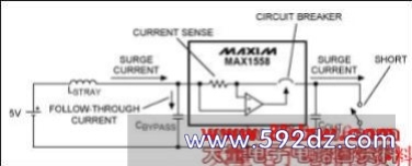
Figure 1. This diagram shows the current path during a hard short and the path for the follow-through current that is driven by stray inductance.

Figure 2. This plot shows the short-circuit performance with a 10µF for CBYPASS. The VIN trace shows that the input soars to 8.6V due to follow-through current.
Looking at Figure 2 we see that the input current (IIN) rises very rapidly to 48.8A, then limits due to resistance. When the switch turns off, we can measure the rate at which the current slews down. With Iin slewing down at 20A/µs and VIN soaring to 8.6V (VMAX), we empirically compute the circuit inductance to be:
(VMAX - VIN) = di/dt × LSTRAY
With VMAX - VIN = 3.6V, and di/dt = 20A/µs, LSTRAY = 180nH.
So with E = ½ × LSTRAY × I², at the end of a fault there is 214µJ stored in LSTRAY. Bypass capacitance is needed to absorb this energy and limit voltage rise. A 10µF input cap with an initial charge of 5V has some initial energy stored:
½ × C × V² = E
Now, assuming that all of the stored energy in LSTRAY will end up in the input cap CBYPASS, then;
Initial Energy + Stray Energy = Final Energy
125µJ + 214µJ = 339µJ
339µJ is then the final energy in the input capacitor, with:
½ × C × V² = E
or
½ × 10µF × V² = 339µJ
Solving for V, V = 8.23V. This closely agrees with the measured value of 8.6V in Figure 2.
Now, if the input bypass is reduced to only 0.1µF, the input voltage can rise up to destructive voltages. So, this time with:
Initial Energy + Stray Energy = Final Energy
1.25µJ + 214µJ = 215µJ
and
½ × 0.1µF × V² = 215µJ
Solving for V, V = 65.6V!
This process, of course, will damage a part rated for 5.5V. The waveforms during this hard short are shown in Figure 3. Notice that the output also soars to 9.8V. This occurred because the short was removed before the switch turned off, which also accounts for the high di/dt in this test. Normally the di/dt is governed by the turn-off characteristics of the power device. With a USB port, the circuit is dependent on the end user―a situation that is anything but controlled. An extremely fast turn-off like this could be caused by an intermittent cable, bad connector, or, as in this case, connection bounce associated with a mechanical connection.
标签:电源管理,高级电源管理大全,电源管理ic,电源管理
上一篇:555组成电压反转电路图
《Surge Testing Solid-State USB》相关文章
分类导航
- 最新《电源管理》
- ・ 温度补偿式单象限对数变换器
- ・ 具有3.3V和5V输出的dc变换电路
- ・ 250W变换器
- ・ 数字变换器
- ・ 相邻脉冲等延时电路图
- ・ 闸门脉冲发生器电路图
- ・ 正弦波发生器电路图
- ・ 指数式压控振荡器电路图
- 热门《电源管理》
- ・ 温度补偿式单象限对数变换器
- ・ 多种波形发生器电路图2
- ・ 交流线路生升压器
- ・ DCDC转换器让您的电力更持久
- ・ 逆变电路
- ・ 下一代汽车照明电源
- ・ IP3842N典型应用电路图
- ・ 逆变器原理